Digital Potentiometer Circuit Working Types and Its Applications Circuit Diagram It also makes the circuit diagram a little bit nicer-looking I think. Wiring Example #3: Potentiometer as Volume Control. This example uses all three pins of the potentiometer to create a simple way of adjusting the volume of an audio amplifier.
This design of digital POT is considered as an illustration of linear taper. The total number of steps in this resistive ladder defines the resolution of the device. The below picture shows the digital potentiometer circuit diagram in ladder design. The digital resistors are regulated through up/down signals or by protocols like SPI and I 2 C. Digital potentiometers find applications in various electronic systems, including audio equipment, instrumentation, programmable voltage and current sources, motor control, and calibration circuits. They offer flexibility, versatility, and improved functionality compared to traditional potentiometers, especially in scenarios where precise

Digital Potentiometer Fundamentals Circuit Diagram
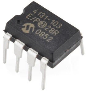
the digital potentiometer. RAB is the nominal resistance across the entire potentiometer, from pin A to pin B. RBW is the resistance between pin B and pin W of the digital potentiometer. n is the number of digital potentiometer bits. For the MCP4XXXX family of potentiometers, the number of bits is eight. Dn is the digital code in decimal form

The digital potentiometer (digipot) is a processor-controlled, • The required resistance value, often called end-to-end resistance, is determined by the design considerations of the circuit. Vendors offer resistances between 5 kilohms (kΩ) and 100 kΩ in a 1/2/5 sequence with some other intermediate values.

Basics of Potentiometers with Arduino Circuit Diagram
The typical potentiometer will have 3 pins, two power supply pins (+5V and GND), and one pin that connects to an analog input pin on your Arduino to read the value output. To learn how to read data from a potentiometer, and display it in the Serial Monitor, visit the Analog Read Serial example. Hardware Required. Arduino board; Potentiometer